Reverse Engineering the Zycomm FM5016 by M9IPM & G4XRA
On the right of the image below is the RF section for the radio which has been detached from the main radio.
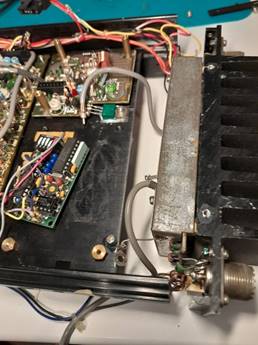
On this model there is only one transmitter even though there are 2 PL259 sockets.
There are two screened cables. A to the top of this picture and B at the bottom.
B is fed from the board at the top centre of this picture which we hypothesise is the preamplifier/filter board which is in turn fed by the PLL board. The PLL board has been identified by the PLL chip and the EEPROM.
Our hypothesis regarding the preamplifier/filter is based on the following.
1. Position in circuit chain.
2. Presence of amplifier
3. Presence of filtering congruent with selectivity to reduce harmonics from PLL circuits.

A connects to the input of the receiver board, bottom right. RF output power
The top left shows the local oscillator input from the PLL board.
Power Amplifier Description
The RF amplifier is based around the Mitsubishi C2630 50W VHF transistor.
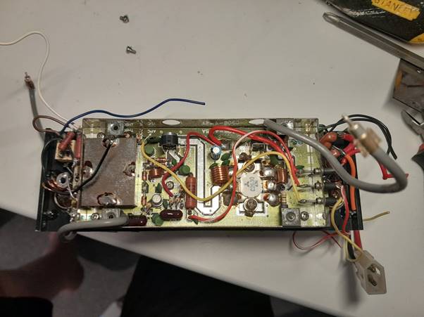
Needing more work…. There is also a Motorola sa92352 ?? transistor which needs further research. With the proximity to the receive out cable the screen box could be a transmit/receive switch yellow wire?